My Projects
Over the years I have completed numerous projects ranging from computational fluid dynamics to structure optimisation, the following is a brief glimpse of some of my main projects.
- 4th AIAA High Lift Prediction Workshop
- Flow Control on a Multi-Element Aerofoil
- Aeroacoustics of Tandem Cylinders
- Support System Design of the UWE Subsonic Wind Tunnel
- Mathematical Model for a Simple Flapping Cycle
- Redesigned Engine for B-52 Stratofortress
- Aircraft Flap Actuator Design
- Piper PA-28 Stability Derivatives
- Analysing a tapered beam structure using analytical method
- Research Mapping
- Design of a Machine Vision System for the Inspection of Defects on Aluminium Black Plates
4th AIAA High Lift Prediction Workshop (Link)
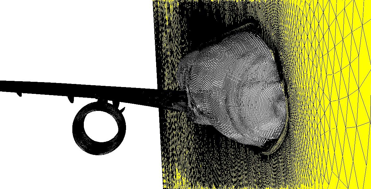
During my final year at University I joined the UWE team Participating in the 4th High Lift Prediction Workshop setup by NASA and the AIAA. As part of my final year dissertation I performed simulations on cases set out by the workshop, which involved investigating the capability of computational fluid dynamics (CFD) to resolve flow features found in high lift aerodynamics. Commercial code ANSYS Fluent is used in conjunction with the Spalart-Allmaras turbulence model and RANS and hybrid RANS/LES methods to predict the flow field around the NASA Common Research Model in a High Lift Configuration (CRM-HL).
The rpedicted solutions form the simulations were compared to NASA code FUN3D in order to verify the implementation of the Spalart-Allmaras turbulence model. Results found that Fluent had good agreement with FUN3D on coarse meshes however results began to differ as the mesh was refined.These differences were attributed to to different levels of iterative convergence, differences in the order of spatial discretisation and also different user practises.
Further simulations were performed to at various angles of attack using RANS and the hybrid method Delayed DES to compare how the methods perform. Solutions using the different methods showed very similar results with DDES showing a slightly greater lift curve. However, with the DDES simulations sometimes taking days to reach a statistically steady solution the slight improvement in accuracy was demmed not worth the larger computational cost.
Flow Control on a Multi-Element Aerofoil
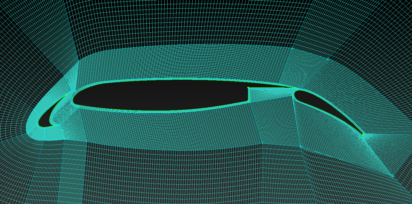
During my third year at University a gained an interest in how flow control methods can be used to improve the aerodynamic performance of aerofoils. In this study the separation control and lift-enhancing capabilities of steady blowing on the upper surface of the multi-element airfoil 30P30N was been investigated using 2D numerical methods. Simulations were run using typical take-off/landing configuration and conditions using steady RANS and the SA turbulence model. Three different cases were tested, one baseline case with no blowing and 2 cases with steady blowing each having different momentum coefficeints.
Results found that the baseline case had flow separation occur on the flap trailing edge at 8.23°, after the addition of blowing this separation was prevented. The baseline aerofoils stall was not due to any separation on the upper surface. The use of blowing increased maximum lift coefficient by up to 0.29 at the stall angle, however the stall angle did not move. The greatest lift increases were seen at low angles of attack, with the highest increase of 0.45 occurring at 8.23°. The addition of steady blowing improved the aerodynamic performance of the airfoil by preventing separation where it was present and shifted the lift curve up therefore increasing the maximum lift coefficient. However, the incremental increase in lift would probably not be worth the cost of additional weight and complexity the system would add
Aeroacoustics of Tandem Cylinders
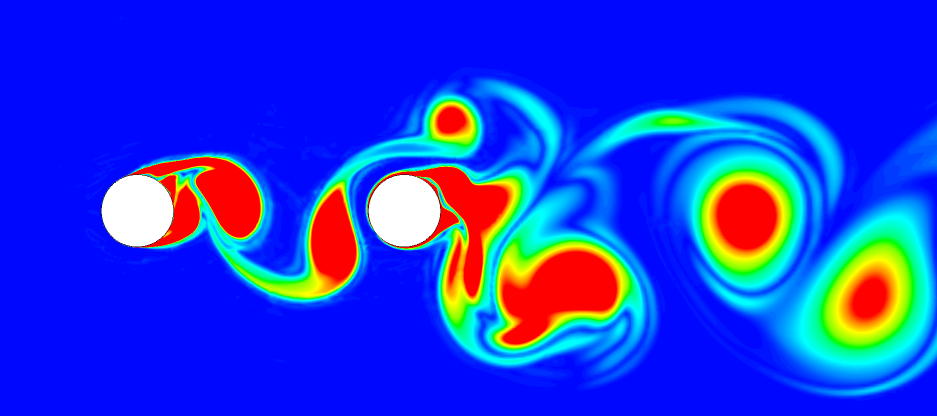
In this study numerical simulations were performed to investigate the noise generated from flow around a single cylinder and a tandem cylinder configuration at Re = 89,000 and M = 0.2.
ANSYS Fluent is used to perform Unsteady RANS simulations with the k-omega SST turbulence model. The method used is validated on the baseline cylinder case by comparing solutions with both experimental and numerical results. The setup is then repeated on a tandem cylinder case where a downstream cylinder is placed at 3.7D behind the upstream cylinder. The farfield noise is analysed using the Ffowcs William Hawking's Method.
Further simulations are also done using Delayed Detached Eddy Simulation method. Results found that the sound pressure level peak of 90dB occurred at the shedding frequency of the cylinders, where the Strouhal number corresponded to 0.195. SPL is much greater at higher frequencies with no distinct peaks and is mostly broadband, likely due to the range of eddies. DDES solutions provide better prediction of the flow as they resolve the larger eddies in the wake and predict higher levels of SPL compared to URANS.
Support System Design of the UWE Subsonic Wind Tunnel
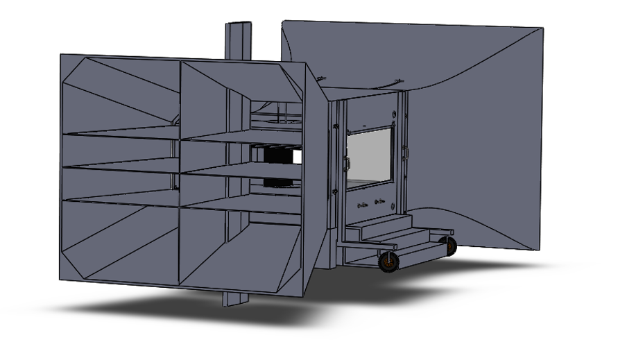
This design project involved creating, redesigned and evaluating new sub-system designs and support mechanisms at the University of the West of England’s subsonic wind tunnel which is due for refurbishment. The redesign work includes various conceptual designs, and detailed designs for a new sting support, side wall support and 2D support system modifications. Additional features such as the probe traverse system, a removable wall, and re-work of the diffuser design was also done. The project includes conceptual designs, preliminary design, detailed design, an aerodynamic impact assessment review as well as a section outlining some cost estimates and project management elements of the project undertaken.
In summary of the final design configurations, the final design involves a sidewall system fixed to the ceiling of the test section, feeding straight into the overhead balance; a 2D system which uses the sidewall pitching and balance mechanisms, with a secondary nozzle for better aerodynamics and true 2D flow; sting system mounted onto a vertical pillar in the diffuser; probe traverse system which can be adapted to fit on the ceiling of the 2D test section or the main test section ceiling for 3D experiments; the use of the existing strut support system is not interfered with across any of the new designs; and finally a re-work of the diffuser design to best suit the chosen sub-system design configurations. All configurations are able meet the minimum range of motion requirements stated in the user requirements.
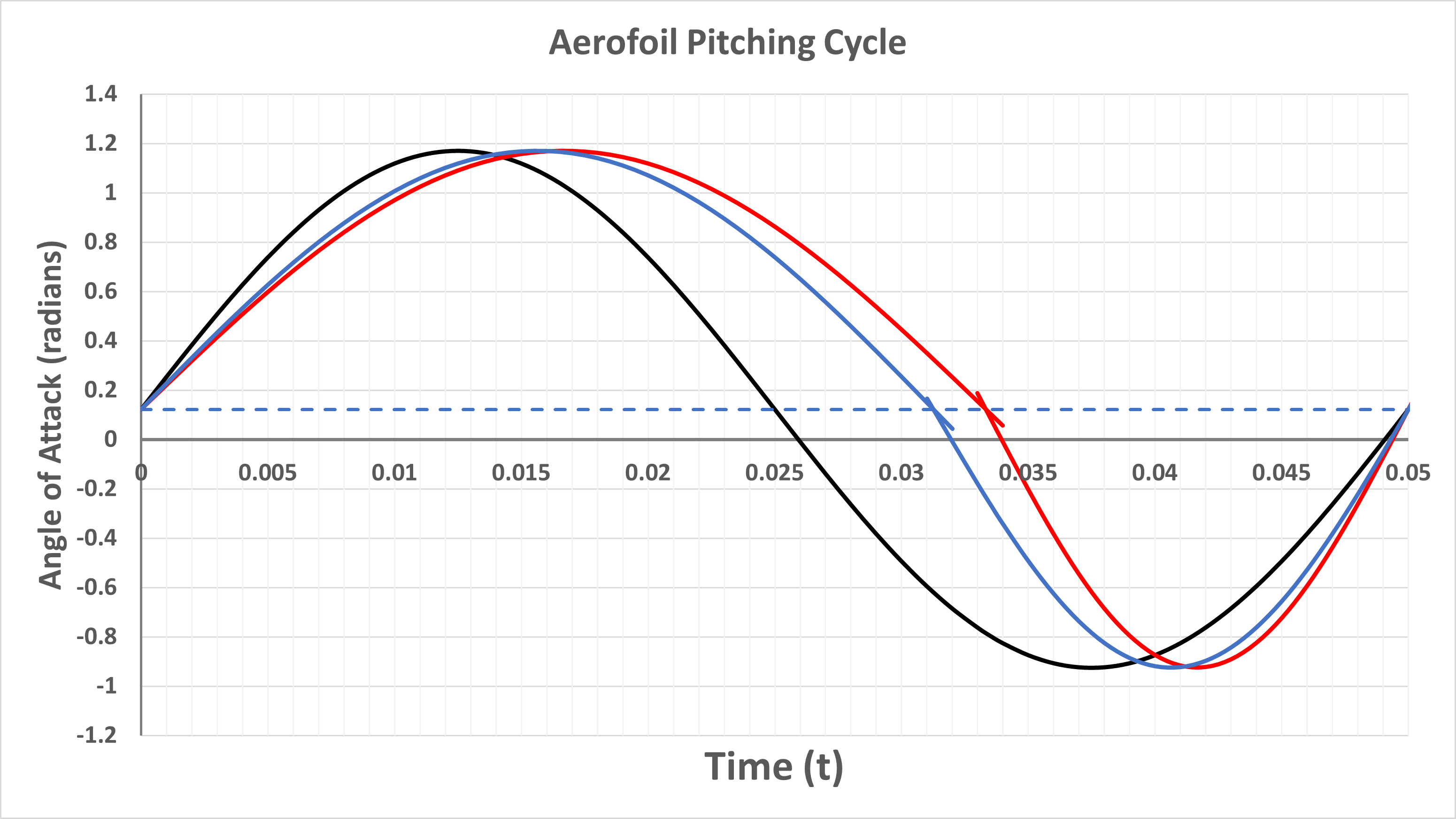
Mathematical Model for the Aerodynamics on an Aerofoil in a Simple Flapping Cycle
This project involved creating a simple preliminary design for a small flapping drone which would be used to aid rescue missions in cases of fire or where earthquake or floods have occurred. The drone would be able to navigate through narrow spaces and withstand high gusts and would be smaller than a typical model quadcopter.
Insects have remarkable flight characteristics therefore there have been many attempts to replicate their flying abilities. Similarly, this preliminary design will be based on locust due to their collision avoidance capabilities. Open literature was used to find initial dimensions, flapping frequencies and typical aerofoil profiles. Two aerofoils were chosen for comparison, one conventional (NACA 4305) and one corrugated (based on locust wing). The corrugated aerofoil is designed with the same maximum camber and maximum camber location as the NACA aerofoil for better comparison
The mathematical model used for aerodynamics is thin aerofoil theory. Where the aerofoil section is modelled by a vortex sheet, this vortex sheet consists if a distribution of vortices along the camber line to give quick and reasonable estimates for the lift and moment coefficients. The simple flapping cycle is modelled using a pitching movement around the quarter chord where the upstroke equals the downstroke. Additional test cases where investigated in which the upstroke time is different to the downstroke time.
The results show that the lift coefficient at fixed angle of attack of 7° for the corrugated aerofoil was greater than the NACA 4305, 1.29 and 1.19 respectively. For case 1 the downstroke time was increased by 33.33%, this corresponded to a 100% increase for the corrugated aerofoil and 117% increase for the NACA aerofoil. For the second case with a shorter downstroke the lift coefficient increased by 81% and 88% for the corrugated and NACA aerofoils. This shows that the first case with the longer downstroke produced the greatest lift increase compared to the simple flapping cycle. For both cases the NACA aerofoil had a greater increase in lift compared to the corrugated aerofoil. Therefore, NACA aerofoil is chosen as it had the greatest lift increase from the fixed angle of attack.
As mentioned before lifting line theory produces quick and reasonable results for pitching and lift coefficients and could model different upstroke/downstroke times. The model could also be changed to incorporate heaving
and a change in the phase between the plunging and flapping. Also changes in the shape of the aerofoil. However, lifting line theory is not accurate enough
for these cases as flapping movements can be complex and the flow is unsteady.
Redesigned Engine for B-52 Stratofortress
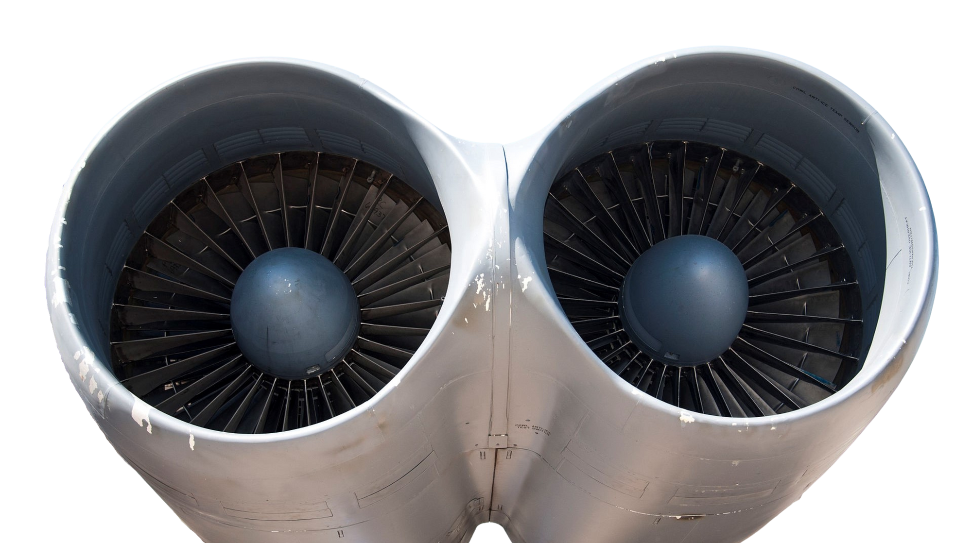
The primary task was to design a 3-spool unmixed flow turbofan to replace the current JT3D engine on the B52 Stratofortress. To do this the software GasTurb was used to design the new engine and ANSYS CFX was used to simulate the combustion process of the proposed engine. The main aim of the new engine was to reduce the fuel consumption by at least 10% of the current JT3D engine. This task required varying parameters such as intake mass flow rate, pressure ratios, burner exit temperature and BPR using GasTurb to create an engine that meets the requirement of the on and off design while also achieving the lowest TSFC and be within the limitations given.
Aircraft Flap Actuator
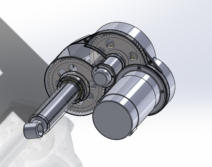
The Objective of this project was to design a flap actuator for use on a light aircraft. The actuator is comprised of a sealed housing, motor, 4 gears, bearings, shaft and power screw. The project report includes the design methodology and the resulting final design, including screenshots of the final CAD Model. The design process is outlined, including material selection, design embodiment CAD modelling and the end result. Key design outputs are included for each component of the actuator. The final result is a fully designed and modelled flap actuator intended to take on a max force of 7700N.
As the actuator is to be used on an aircraft there are a number of technical specifications for the design to meet, such as reliability, safety factors and max component sizes. The use of CES software allowed the most optimal material to be selected taking into account important property requirements such as strength and cost. The final design is viable as it meets the technical specifications required for the actuator. The actuators case is designed to be as compact as possible to reduce the weight and space it take up on the aircraft, while the gearbox is also compact and meets size and safety requirements. Overall the designed actuator is a viable solution for this design problem.
Piper PA-28 Stability Derivatives
This Project focuses on the assessment of the primary dynamic modes of the Piper PA-28 using numerical models to produce simulations of aircraft motion and assess the stability of the aircraft. The main aim of this report was to compare the results of the different methods using theory and verify the values obtained. The methods used are Flight Test, Merlin Flight Simulator, Linearized Small Disturbance Equations of Motion (LEOM), Analytical, Approximation and Simplified analytical. For each method the modes assessed are Phugoid, Short-Period, Dutch Roll, Roll Subsidence and Spiral.
Project Objectives
• Analyse Flight test Cards to obtain natural frequency and damping ratio.
• Extract and obtain results from Merlin Simulator data.
• Obtain 19 Stability derivatives (Longitudinal and Lateral).
• Compare dynamic characteristics of the PA-28 with different methods
Analysing a tapered beam structure using analytical method
This report focuses on analysing a tapered beam structure using analytical method and finite element analysis method. Hand calculations of reaction forces, principle stresses and displacement for the proposed case are calculated, followed by a comprehensive study using the computer software Abaqus. Graphical representations were offered for better a visualisation regarding the displacement of the beam using contours. In order to determine an optimised structure, Abaqus has been used to analyse the beam structure while modifying dimension parameters within the constraints, finding the ones with the highest impact. Optimisation was also done using analytical method in Microsoft Excel.
Design of a Machine Vision System for the Inspection of Defects on Aluminium Black Plates
This report outlines the design of an inspection system for black plate components. A script is designed to analyse the component and decide whether it has the correct features and dimensions using machine vision software Vision Builder. The design methodology is described, and the script is thoroughly tested and evaluated.
The inspection system is required to examine objects and decide whether they pass or fail depending on the values taken from the image capture. The vision systems lighting, lens and camera must be suitable for the task in hand, factors such as smallest feature defect to detect, measurement accuracy, surface finish, object size and speed needed for image capture and processing all effect the decision on the types of lighting, lens and camera to use thus the effects of these capture conditions on the accuracy of the inspection are investigated and discussed.
As the component being tested is produced in high volume human manual inspection is not feasible due to the reliability, repeatability and speed required, therefore methods of automated inspection are investigated. Methods for non-destructive testing are also assessed in order to find the best method of internal inspection for the current application. Finally, a complete inspection system is presented which includes multiple sub-systems, some of which are the machine vision and internal defect inspection. As a result of the findings in this report, recommendations are given on cameras and other components that can be used in the system.
The effects of capture conditions were studied and found to be crucial component in accurately inspecting a component. Ideally Lighting would be set up around the object to eliminate shadows and the camera would be set at the correct working distance and use the right lens to reduce capture errors. The created script was able to correctly measure features however had a tolerance of 4mm. Through the use of back lighting major features are easily recognised however surface defects such as cracks are not identified.
An investigation into different methods of thickness and internal defect detection have resulted in the recommendation of the electromagnetic acoustic transducer testing method, this was chosen due to its ability to inspect a high volume of components relatively quickly, this choice was made considering there were no cost constraints.