Support Systems for Subsonic Wind Tunnel

The aim of this project was to design support system mechanisms for the refurbishment of the University of the West of Englands subsonic wind tunnel.
The systems designed are:
- Sting Support
- Side Wall Support
- 2D Support
- Traverse system
- Diffuser nozzle
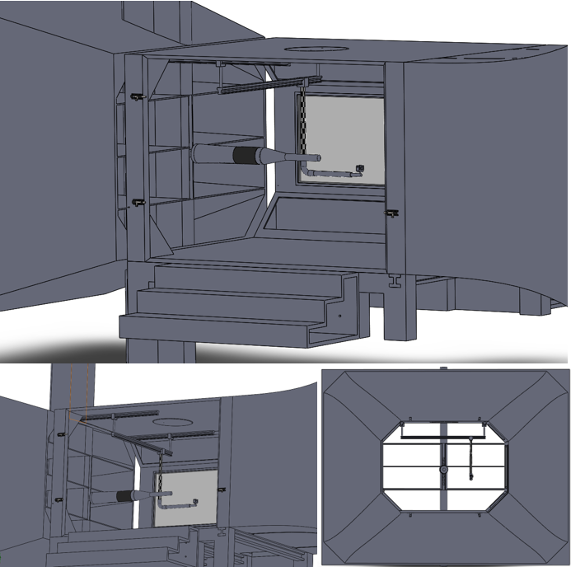
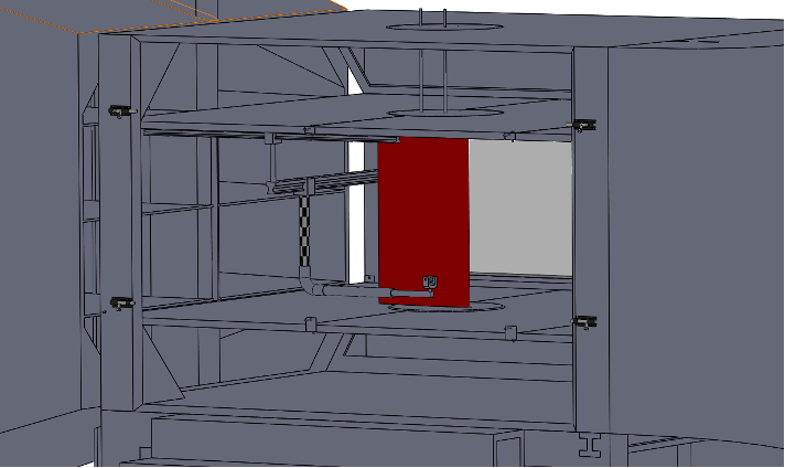
Sting Support System
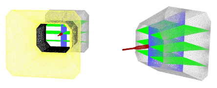
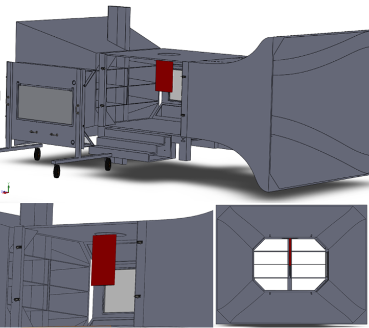
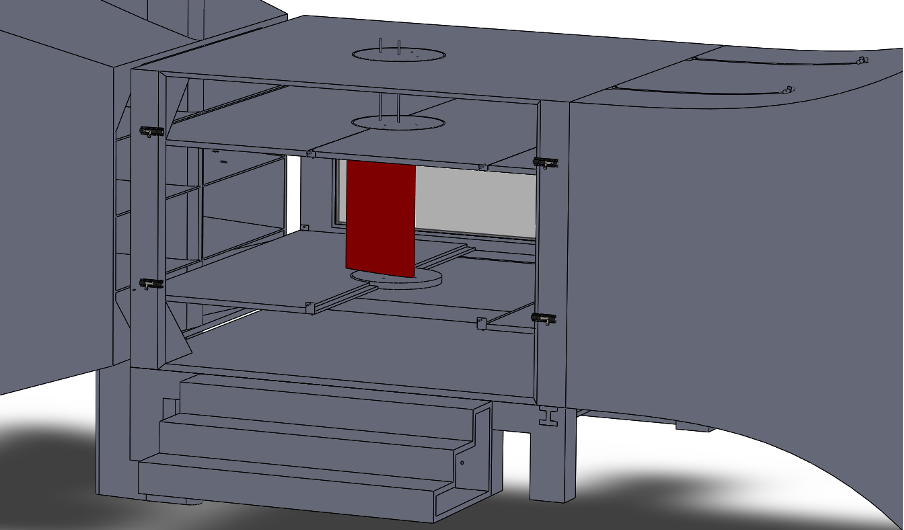
A sting is a fixture where the model is mounted on a shaft which is usually at the downstream end of the model so that there is less disruption to the flow over the model.
The user requirements for the sting system are a pitch range of -10 degrees to 60 degrees and a roll range of -182 degrees to 182 degrees.
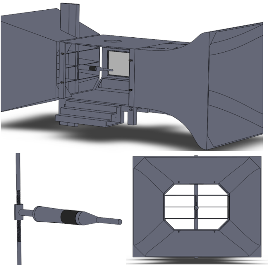
Initially, six preliminary designs were created which were narrowed down using a selection matrix from criteria developed from the user requirements. Three concepts were identified to be the most viable and went on the the next stage where further evaluation was done as well as discussions with stakeholders on the feasibility of each of the concepts. The final design was a mix of two concepts, it involves a central vertical pillar to house the mechanisms and a perpendicular shaft where models would be mounted. this design was chosen due to several reasons: ease of removability in order to change the wind tunnel setup, reduce wind tunnel blockage and to maintain the support systems stiffness.
The designs were then created using Solidworks CAD and can be seen in the pictures below.
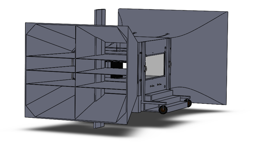
Sidewall Support System
The sidewall system mounts half models to the side of the wind tunnels wall
2D Support System
The 2D mounting system runs from the ceiling of the wind tunnel to the floor and is used to mount 2D models.
Traverse System
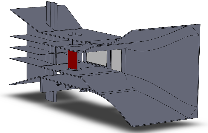
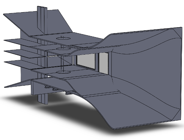
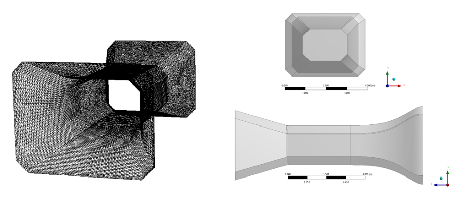
Wind Tunnel Diffuser Nozzle
After the test section, the flow enters the diffuser where the air is expanded and slowed down. The wind tunnel has a wide angle diffuser design which allows a greater nozzle contraction ratio and improved flow quality in the test section, however it can introduce additional losses and suffer from large boundary layer separation which was confirmed in preliminary CFD simulations. Thus, in an effort to prevent the flow separation screens are introduced in the diffuser design.
Computational Fluid Dynamics
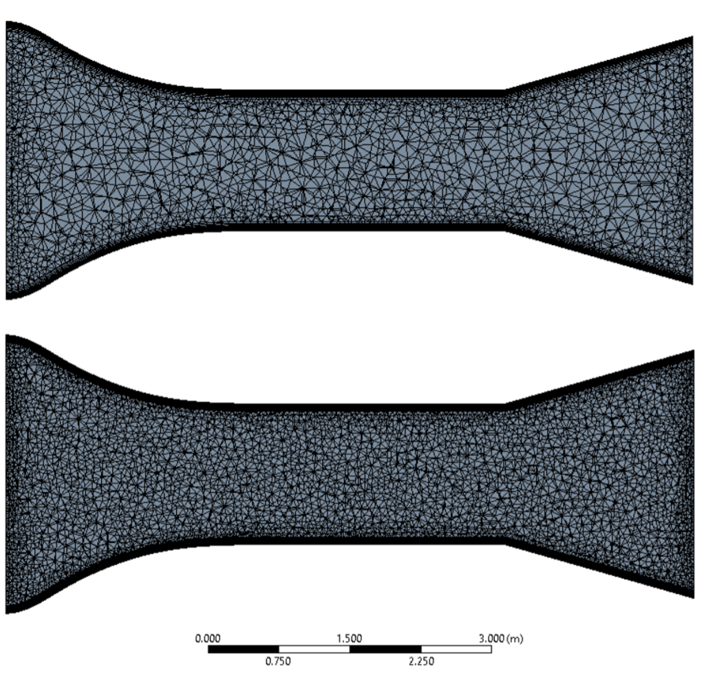
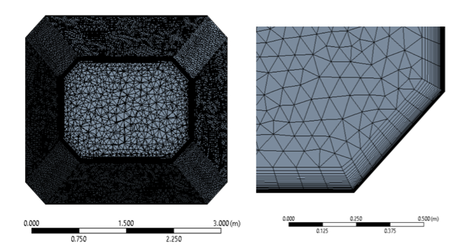
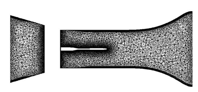
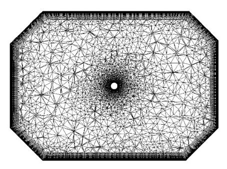
In this study the simulations are performed using commercial code ANSYS Fluent. In order to use the CAD model for flow simulations, the level of detail was reduced for easier mesh generation and to reduce the number of cells and thus reduces simulation time.
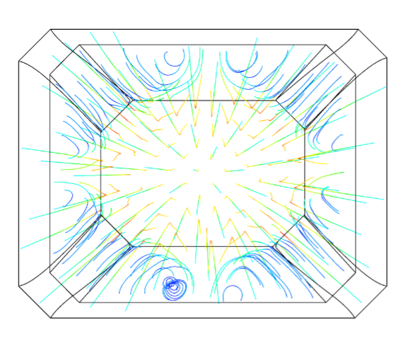
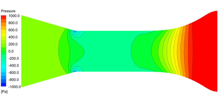
As the test section is the primary area of concern, a simplified approach is used. In order to keep the number of cells reasonable and capture relevant flow development the simulation domain consists of the contraction nozzle, test section and diffusor.
In the wind tunnel, the total pressure decreases through the test section due to pressure losses, the pressure lost is then compensated for by the fan. To have the same static pressure in the test section as the local atmospheric pressure, there is a breather at the back of the test section, however for simplicity it is not modelled in the simulations.
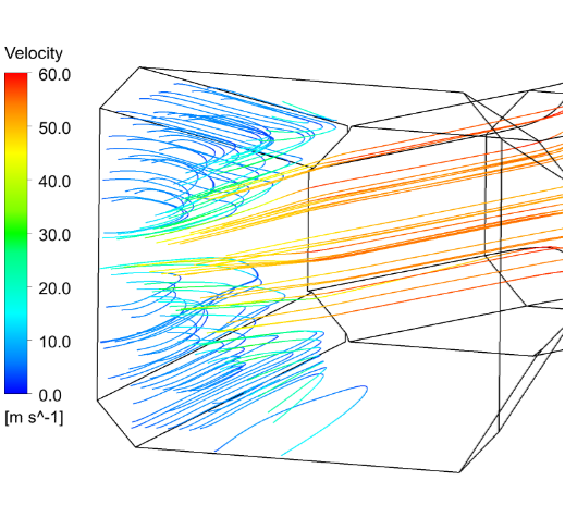
Initially the empty tunnel is considered, parts are then added to investigate the effects of each component on the flow field inside the tunnel.
Empty Wind Tunnel
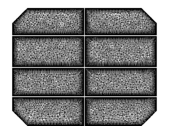
The simulations used an unstructured mesh with inflation layers along the walls in order to capture the behaviour of the boundary layer. The grid topology consisted of structured prisms on the wall with the central region consisting of unstructured tetrahedral elements.
A grid resolution study was done to identify the impact of the mesh resolution on the results. As the simulations don't use wall functions the boundary layer is resolved directly, thus the \(y^+\) on the walls is targeted to be 1 or less to meet the requirements of the turbulence model.
Grid Convergence Index (GCI) was used to aid the grid resolution study. The test section pressure was used to study convergence, using Richardson extrapolation the predicted solution for minimum static pressure on an infinitely fine grid was -117.22 Pa. The figure shows how the solution approaches the extrapolated end value as the grid is refined.
The simulation used mass flow inlet and pressure outlet as they gave the closest atmospheric pressure in the test section. The outlet mass flow was monitored to check conservation of mass. This setup was then used for the rest of the cases.
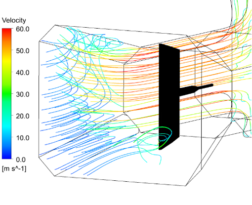
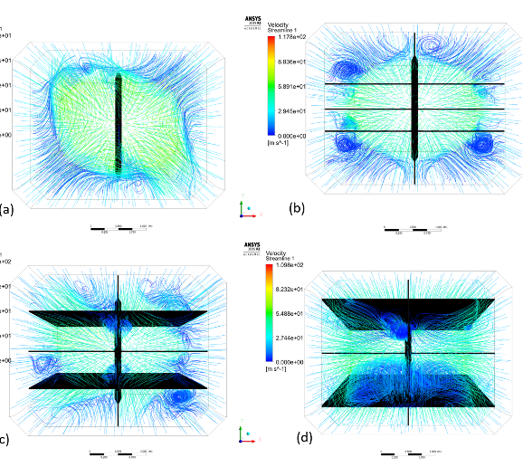
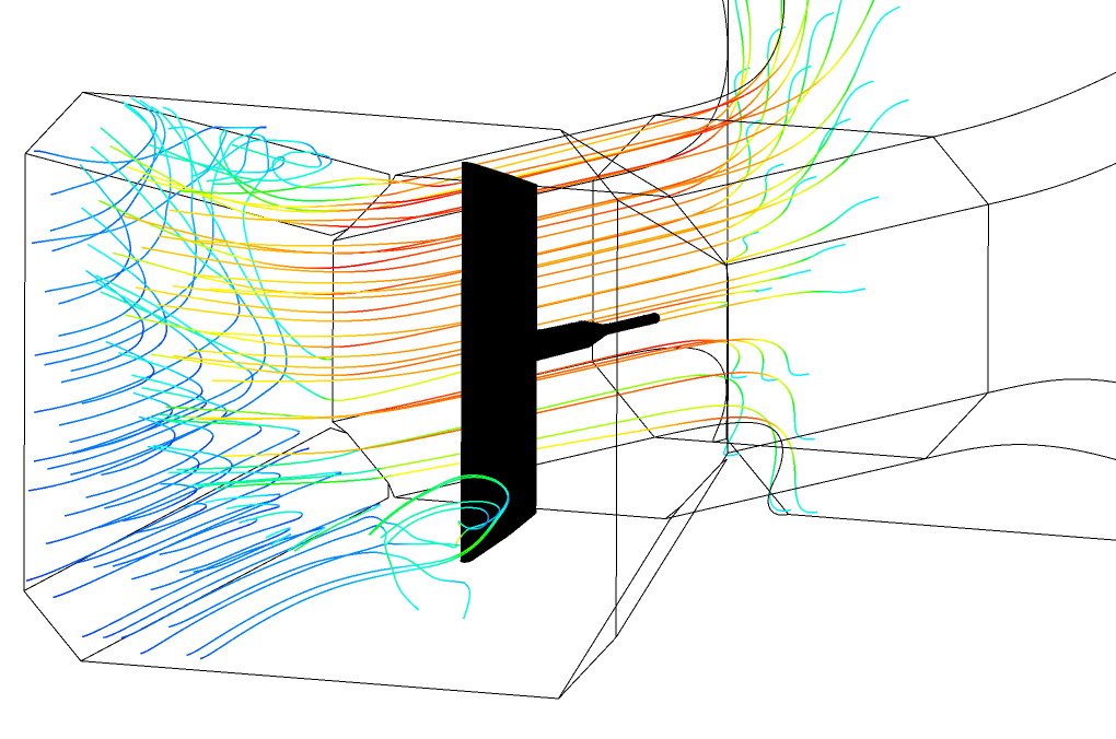
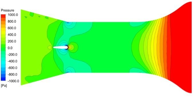
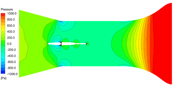
Sting System with Model

Diffuser Design Testing